Installing a solar panel system with a battery at home might seem complex, but understanding the electrical diagram is the first step towards a successful installation. This guide helps you demystify diagrams, identify essential components, and choose the type of installation that best suits you. You’ll discover how a solar panel with a battery can provide you with greater energy independence.
Key Takeaways
- The electrical diagram of a solar panel with a battery shows how all the elements are connected. It’s important for safety and for following regulations.
- The main components are the solar panels that produce electricity, the inverter that transforms it, the batteries that store it, and the charge controller that protects the batteries.
- There are different diagrams depending on whether your installation is connected to the public grid (on-grid), completely independent (off-grid), or a mix of both (hybrid).
- Proper sizing of cables and protection devices, such as circuit breakers and surge protectors, is necessary for a safe and efficient installation.
- Using design software or online templates can help create an accurate diagram, avoiding common mistakes like incorrect connections or improper sizing.
Understanding the Electrical Diagram of a Solar Panel with Battery
Definition and Role of the Photovoltaic Diagram
The photovoltaic electrical diagram is essentially the blueprint for your solar installation. It graphically represents how all the components are connected to each other: the panels, the inverter, the batteries, and even your home’s electrical panel. Its primary role is to show the flow of electricity, from its production by the sun to its use or storage. Without this diagram, installing a system would be like trying to build a house without plans: risky and potentially inefficient. It is the foundation for any installation, whether for a single-family home or a larger building. It allows for visualization of the entire system and ensures that everything will function as intended. It is a technical document that serves as a reference throughout the life of your installation, from initial setup to future maintenance. It is often requested by authorities for project approval and by energy providers for grid connection. This document is therefore the starting point for a successful and compliant solar installation. It allows for visualization of the connections between the different components, which is essential for a good understanding of the system to see the role of the diagram for a safe installation.
Importance of the Diagram for a Safe and Compliant Installation
A well-made electrical diagram guarantees an installation that complies with standards and is safe for you and your household. It helps avoid wiring errors, such as polarity reversals, which could damage your equipment or, worse, cause an accident. Installers use it as a guide for correct assembly, thereby reducing the risk of errors. Furthermore, this plan is often a requirement for obtaining necessary permits and for grid connection. It ensures that your system complies with current regulations, which is important for the longevity of your installation. It also serves as a reference for future interventions, whether for maintenance or a potential expansion of your system. In short, the diagram is the guarantor of the safety and compliance of your solar project.
Reading and Interpreting Standardized Electrical Symbols
To read an electrical diagram, you need to know the language of symbols. Each component, such as a solar panel, an inverter, or a battery, is represented by a specific icon, following international standards (like IEC EN 60617). For example, a rectangle with an arrow might indicate a solar panel, while a triangle with a bar often represents an inverter. Solid lines show the main electrical connections, and dashed lines can indicate control or communication signals. Understanding these symbols allows you to follow the path of electrical current through the entire system. Arrows on the diagram indicate the direction of energy flow, which is very useful for understanding the overall operation and for diagnosing potential problems. Here are some examples of common symbols:
- Solar Panel: Often represented by a circle with a cross inside, or a rectangle with an arrow.
- Inverter: Generally a rectangle with an arrow pointing outwards or a specific symbol.
- Battery: A series of short connected rectangles, representing cells.
- Circuit Breaker: A switch with a lever and sometimes a tripping mechanism.
Knowing how to decode these symbols is key to understanding how your solar installation is designed and how it operates daily. It’s a bit like learning to read a map to avoid getting lost. The electrical diagram is therefore an indispensable tool for anyone wishing to understand their photovoltaic system to learn more about the components.
Essential Components of a Solar Installation with Storage
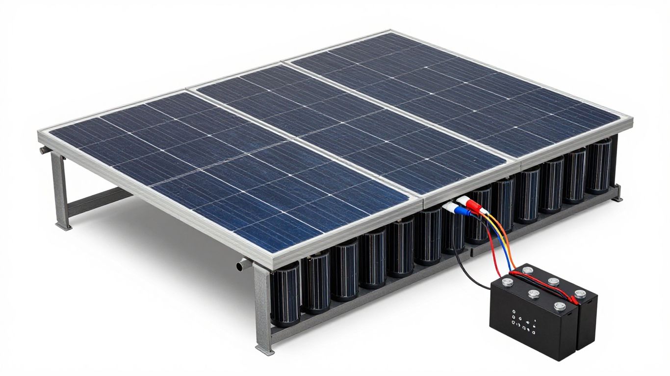
For a solar installation with a battery to function correctly, several key elements must be present and well-connected. It’s a bit like assembling a puzzle; each piece has its role.
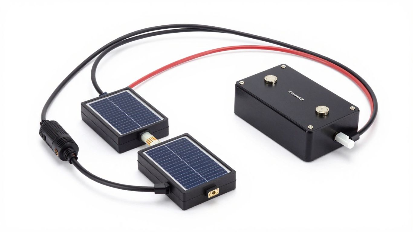
Photovoltaic Modules: The Heart of Energy Production
These are the panels you see on rooftops. Their job is to capture sunlight and convert it into electricity. This electricity is initially in the form of direct current (DC). The amount of energy produced depends on their size, efficiency, and of course, the amount of sunlight they receive. They need to be well-oriented and free from shade to perform at their best.
The Inverter: Converting Direct Current to Alternating Current
The electricity produced by the panels is direct current, but our home appliances run on alternating current (AC). This is where the inverter comes in. It performs this essential conversion. There are different types of inverters, such as central inverters or micro-inverters that handle each panel individually. The choice depends on the configuration of your installation. For safe integration into your electrical system, it is connected to your panel via specific protection devices like a protection box.
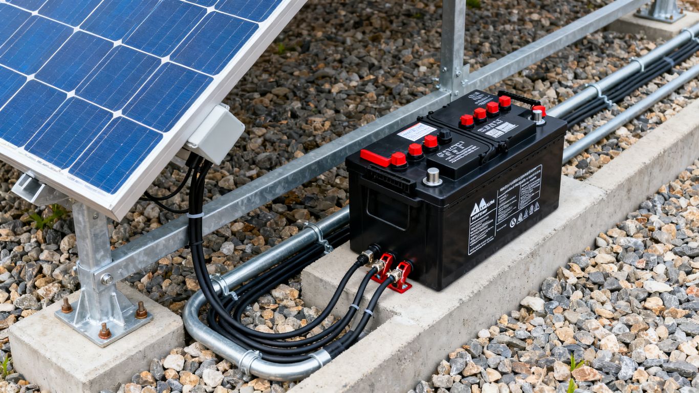
Storage Batteries: For Increased Energy Independence
This is the star of installations with storage. Batteries are used to store surplus electricity produced during the day for use when the sun is no longer shining, such as in the evening or at night. This allows you to be less dependent on the electrical grid. There are several battery technologies, such as lead-acid or lithium, each with its advantages in terms of lifespan and capacity. The necessary capacity must be carefully calculated based on your consumption and the desired number of days of autonomy.
The Charge Controller: Optimizing and Protecting Batteries
In systems that use batteries, the charge controller is very important. Its role is to manage how the batteries are charged by the panels. It ensures that they are neither overcharged nor deeply discharged, which could damage them. It also optimizes energy transfer. MPPT controllers are more efficient because they track the maximum power point of the panels, especially when sunlight conditions change.
Each component plays a specific role in the solar energy production and storage chain. Their proper selection and compliant installation are key to a high-performing and durable installation.
Typical Diagrams Based on Photovoltaic Installation Type
The electrical diagram for your solar installation is not universal; it changes depending on how you plan to use the energy produced. Understanding these differences is key to choosing the configuration that best suits your needs.
Diagram for a Grid-Tied Installation (On-Grid)
This type of installation is the most common for individuals. The energy produced by your solar panels is first consumed by your home. If you produce more than you consume at a given moment, the excess is fed into the public grid. Conversely, if your production is insufficient, you draw from the grid. The diagram must therefore clearly show the connection between your panels, your inverter, your home electrical panel, and the Linky meter (or equivalent) that manages bidirectional flows. Specific protections for grid connection, such as surge protection on the AC side, are also detailed here. This solution helps reduce your electricity bill and, in some cases, allows you to benefit from payment for the energy fed back into the grid. You can find examples of diagrams for this type of installation in various technical guides.
Diagram for an Off-Grid Installation
Here, the goal is complete independence from the public grid. Your installation must therefore be able to cover 100% of your energy needs. The diagram is more complex because it necessarily includes storage batteries. The DC current from the panels powers a charge controller that optimizes battery charging. The stored energy is then converted into AC by an inverter to power your appliances. A backup system, such as a generator, must also be planned for periods of prolonged low sunlight. The management of flows is entirely internal to your site. This type of installation is often chosen for isolated sites or for individuals seeking maximum resilience.
Diagram for a Hybrid Installation
A hybrid installation combines the advantages of the two previous systems. It is connected to the public grid but also has storage batteries. This allows you to consume your own energy, store the surplus for later use (e.g., in the evening), and continue to benefit from the security of the public grid when needed. The inverter in this case is called « hybrid »: it manages the panel production, battery charging/discharging, and exchange with the grid. The electrical diagram reflects this versatility, showing the multiple connections between all these elements. It is an increasingly popular solution for optimizing self-consumption while maintaining a grid connection.
Here is a simplified comparison table of key elements by installation type:
| Installation Type | Specific Components in the Diagram |
|---|---|
| Grid-Tied (On-Grid) | Production meter, specific AC protections |
| Off-Grid | Batteries, charge controller, inverter, potentially generator |
| Hybrid | Hybrid inverter, batteries, grid/storage flow management |
The precise design of your electrical diagram is a non-negotiable step. It not only ensures the safety of your installation and people but also its energy efficiency and compliance with current regulations. Never neglect this detailed planning phase.
Each diagram must be created with care, using standardized symbols for clear reading by all professionals involved in the installation. You can consult diagram templates to help you visualize these different configurations.
Sizing and Protections in a Solar Panel System with Battery
Once you have a clear idea of the components of your solar system, it’s time to discuss two equally important aspects: the correct sizing of each element and the implementation of adequate protections. Neglecting these points can not only reduce the efficiency of your installation but also compromise your safety.
Sizing of Panels and Cables
Sizing begins with the panels themselves. It’s not just about choosing the number of panels, but also ensuring that their voltage and current are compatible with the rest of your system, particularly the inverter and charge controller. For example, the open-circuit voltage of the panels, calculated considering extreme temperatures, must remain within the MPPT range of your inverter. An over-allocation of DC power relative to the inverter’s nominal power is often practiced to compensate for losses and smooth out production, especially in low sunlight conditions.
Regarding cables, their cross-sectional area is crucial. An undersized cable can lead to excessive voltage drop, which reduces the efficiency of your installation, and worse, it can overheat, creating a fire hazard. Therefore, the appropriate cross-sectional area must be calculated based on the cable length, the current it needs to carry, and the acceptable voltage drop. For solar installations, PV cables certified to withstand outdoor conditions (UV, humidity) are generally used. Remember that never connecting or disconnecting solar connectors while they are live is a basic safety rule to avoid electrical arcs.
Essential Protections: Surge Protectors, Circuit Breakers, and Residual Current Devices
Safety is at the core of any electrical installation, and solar is no exception. Protections are there to prevent overvoltages, overcurrents, and insulation faults.
- Surge Protectors (or Surge Suppressors): They protect your equipment against transient overvoltages, particularly those caused by lightning. They exist for the DC side (between panels and inverter) and for the AC side (between the inverter and your home grid).
- Circuit Breakers: They protect circuits against overcurrents (overloads or short circuits) by automatically cutting off the power. They are present on both DC and AC circuits.
- Residual Current Devices (RCDs): They detect current leakage to ground, which can indicate an insulation fault and pose a risk of electric shock. They are mandatory on the AC circuit and sometimes recommended on the DC circuit depending on the configuration.
These devices must be chosen based on the characteristics of your installation (voltage, current) and installed in enclosures suitable for the environment (adequate IP protection rating).
Importance of Grounding and Safety Standards
Grounding is a fundamental protection. It involves connecting all metallic parts of the installation (panel structures, equipment chassis) to the ground. In case of an insulation fault, the fault current is diverted to the ground, allowing protection devices (like RCDs) to act quickly. Proper grounding is therefore essential for the safety of people and the protection of equipment.
It is also crucial to comply with current standards. These standards define the rules for design, installation, and maintenance to ensure the safety and performance of photovoltaic systems. Complying with these regulations means ensuring that your installation is reliable and long-lasting. Do not hesitate to consult technical guides and manufacturer recommendations to ensure your installation meets current standards. For example, the calculation of cable cross-sectional area must follow precise formulas to ensure the safety and efficiency of your installation.
Adhering to sizing rules and rigorously installing protections are not mere formalities. They are the guarantees of your system’s longevity, its optimal performance, and, above all, your daily safety. Each component, each cable, each protection plays its part in the overall balance of your solar installation with a battery.
Design and Tools for the Electrical Diagram
Creating an electrical diagram for your solar panel system with a battery is no small feat. It’s a bit like drawing a house plan before building; without it, you risk getting lost along the way. This document is your technical roadmap. It details precisely how each component is connected, ensuring that everything works together safely and efficiently.
Specialized Software for Diagram Design
To create an accurate and compliant diagram, you will need appropriate tools. Computer-Aided Design (CAD) software are your best allies. Programs like AutoCAD Electrical or EPLAN are often used by professionals for their rich features and library of standardized symbols. For projects more specific to solar energy, software like PV*SOL or PVsyst integrate not only diagram design but also performance simulations. They help you visualize the physical layout of the panels and calculate the expected energy production.
Available Resources and Diagram Templates
If you are not a CAD expert, don’t worry. There are resources to help you. Many solar equipment manufacturers, such as SMA or Fronius, offer standard diagrams on their websites adapted to their products. These templates can serve as a solid foundation for your own design. Online platforms and specialized forums also share diagram examples, sometimes even free tools like QElectroTech, which can be sufficient for simpler installations. Consider consulting the documentation for your equipment; it often contains useful schematic diagrams.
Common Mistakes to Avoid in Diagram Design
When creating your diagram, a few pitfalls need close attention. One of the most frequent mistakes concerns the sizing of cables and protections. Undersized cables can overheat and cause energy losses, or even a fire risk. Similarly, improperly matched protections (circuit breakers, fuses) will not fulfill their role in case of a problem. You also need to pay attention to connections: a polarity reversal between panels or with the battery can damage the equipment. Finally, forgetting certain safety elements, such as surge protectors or adequate grounding, is a serious fault that compromises the safety of the installation and its compliance with standards. A well-thought-out diagram always includes the necessary protections, as shown by the recommended wiring sequence for connecting the battery to the charge controller, then the panels and the inverter for optimal energy management.
The clarity of the diagram is paramount. It must be readable by anyone working on the installation, whether it’s the initial installer, a maintenance technician, or even yourself in the future. Using standardized symbols and a logical organization of the different circuits greatly facilitates understanding and reduces the risk of errors during interventions.
Conclusion
There you have it, you now have a better idea of what electrical diagrams for solar panels with batteries are and the components that go with them. It’s a bit technical, we know, but understanding these basics really helps you see how it all fits together. Whether you’re planning your own installation or just curious, having these diagrams in front of you makes things clearer. Don’t forget that for the actual installation, hiring a professional is often the best option to ensure everything works well and safely. Think about it for your project!
Frequently Asked Questions
What is an electrical diagram for solar panels?
An electrical diagram for solar panels is like a house plan for electricity. It shows how all the elements of your solar installation, like the panels, inverter, and batteries, are connected to each other and to your home. It’s super important for everything to work well and safely.
Why is the diagram so important for my solar installation?
The diagram is crucial because it ensures your installation is done correctly, safely, and complies with regulations. It helps installers connect everything in the right place and serves as a guide if you need to make repairs or modifications later. Without a good diagram, there’s a higher risk of errors.
What are the main components found in a solar diagram with a battery?
In a diagram, you’ll see the solar panels that capture light, the inverter that transforms the current, the batteries that store energy, and the charge controller that ensures the batteries are charged correctly and protected. All these elements are connected according to the diagram.
What is the difference between a diagram for a grid-tied installation and an off-grid installation?
For a grid-tied installation (on-grid), the diagram shows how energy goes to your home and possibly to the public grid. For an off-grid installation, the diagram emphasizes batteries and the charge controller, as there is no grid connection. Both have different protections.
How do I read the symbols on a solar electrical diagram?
Diagrams use special symbols to represent each component, like a rectangle with an arrow for a solar panel or a triangle for an inverter. These symbols are standardized, like a code, so everyone can easily understand where each wire goes and what each part does.
What protections are necessary in a solar system with a battery, and how are they represented on the diagram?
Protections are essential to prevent problems. On the diagram, you’ll find circuit breakers to cut power in case of issues, surge protectors to protect against overvoltages (like lightning), and residual current devices to prevent electric shocks. They are drawn with specific symbols to show where they are placed in the circuit.